|
Here is what I look at when designing a cam profile or analyzing another cam profile. There are other things I look at but these would be the most common.
lobe lift duration at 0.006 duration at 0.020 duration at 0.050 duration at 0.100 duration at 0.200 duration at 0.300 duration at 0.400 duration at 0.500 velocity curve acceleration curve jerk curve radius of curvature pressure angle ramp designs valve lash settings / valve contact This data will usually give me an overall idea of the cam profile and a good comparison with other cam profiles in the same category. The lift table data is fine if the graphs are not available. Making graphs from the data is always an option. The radius of curvature and pressure angles will need to be calculated if that data is not available. Both are important so that information is necessary. There is much more to a cam profile than just the lift and the duration at .050. Unfortunately, that is usually all the information available from the camshaft manufacturer. Some sort of computerized measuring device will be necessary to easily obtain the other data.
0 Comments
I have added an archives to the "CAM TALK" page. It's basically an index to help navigate through all of the entries. It also allows me a way to reference an entry that may relate to something. Hopefully it will be helpful instead of just taking up space. Let me know.
Very nice cam profile graphs can be created from the lift table data if you know how to use Microsoft Excel. It's a little more involved than copy and paste but it's not too difficult. The same information is in the lift table data showing exact numbers but graphs are a good way to analyze a cam profile if you know how to read them. A lot of information can be quickly seen in the graphs. All of the graphs are important to look at but if you only had one graph, the acceleration curve is probably the one to have. In this sample a solid tappet cam profile is symmetrical and the accelerated ramps are designed with the lash settings in the "dip" area. This creates a gentle opening and closing of the valves. This ramp design is usually not necessary on the opening side but if the valve closing speed is not controlled the valve may bounce off the seat or possibly damage parts. The "bowl shape" on the negative side of the curve creates a gentle transition over the nose of the lobe allowing the tappet to easily follow the shape of the lobe. The conservative maximum acceleration will be easy on the valve train and springs. Overall this will be a cam profile that should not cause any unnecessary stress on the valve train. A lot of good information from just a quick look at the acceleration curve. The lift, velocity, and jerk graphs are the other common curves. The lift and velocity curves should both be a nice smooth curve from zero to the maximum valve. Any deviation from the nice smooth curve would indicate a problem with the design itself. The velocity curve will also reflect the type of ramp designs used. The jerk curve will show the changes in the acceleration. Big changes in the jerk curve are normal around the ramp to profile transition. The rest of the curve should be nice and smooth. Any deviation in this area would indicate a design problem. The lift curve needs to have a resolution of four (.0001) decimal places. Three places at a minimum. The velocity curve needs five decimal places (.00001). The acceleration and jerk curves need eight decimal places (.00000001). That is one hundred-millionth! Your software will need to produce the lift table data in the necessary resolutions to create these graphs. Lower resolutions will produce jagged graphs that are useless.  The lift table is the cam profile. I say that a lot. Kind of like the rise and run on stairs, the lift table shows the tappet lift at each degree of lobe rotation. If a dial indicator was placed on the tappet and the camshaft lobe rotated one degree at a time, the dial indicator readings would be the the lift table. Some lift tables may show increments of less than 1-degree. I have previous posts about lift tables so be sure to go back and also read them.
"The lift table shows the tappet lift at each degree of lobe rotation." It is very important to understand that statement. "Tappet lift", is any tappet, not specific. This is the rise (lift) of the tappet. It doesn't apply to any type of tappet, only the lift of the tappet. The same lift table can be for a flat tappet profile or a roller profile. It can be for a roller profile with any wheel diameter. The "tappet lift" is just that, the lift of the tappet. Remember that. The actual tappet used will determine the final shape of the lobe. That is because of the contact point between the tappet and the lobe. The contact point does not stay on the centerline of the tappet. The contact point moves away from the centerline on a flat tappet and a roller tappet. The shape of the lobe and the contact point will determine the tappet lift at each degree of lobe rotation. Obviously if you put a flat tappet on a roller profile or vice versa you will get a different set of specifications. That is because the contact point is different on the flat tappet and the roller, make sense. When someone orders a cam profile design from me they will get a .p file, an .s96 file, and a data sheet with the lift table. All of these are the profile lift table just in different formats for different applications. The .p file is used for the Landis CNC cam grinding machine, the .s96 file is used for most other CNC cam grinding machines. The lift table is part of the data sheet for the cam profile. Other important information is also on the data sheet. Most CNC cam grinding machines that I know of use the lift table to produce the cam profile. Apparently the CNC machines have built-in software to calculate the contact point for the actual tappet being used to produce the cam profile. Sometimes customers will want to convert the lift table to cartesian coordinates (x and y). Using a direct conversion equation from the polar coordinates of the lift table to cartesian coordinates will not work. The contact point for the actual tappet being used must be considered in the calculations. The base circle diameter of the lobe also plays a part. Using a direct conversion will produce a shape that looks more like an inverted roller profile and is of no use. Physically drawing the profile using the lift table and the correct tappet will create the correct lobe shape. I am not a CAD/CAM person but that would probably be the best way to draw it. Back in the day before CNC machines I would create a model lobe by using the lift table and a rotary chuck on a manual milling machine. This was a visually effective way of seeing and understanding the contact point between the lobe and the tappet. In this case the cutter is the tappet and it creates the lobe shape. I would use a flat face end mill for a flat tappet profile and a ball end mill of the correct diameter for a roller profile. Many original roller profile lift tables were used to produce a mushroom flat tappet profile. I just used a flat face end mill cutter instead of a ball end mill. Pretty cool. Today with CNC milling machines the model lobe can be produced using cartesian coordinates. This website may be of help for converting the lift table to the proper x and y coordinates. https://saltire.com/ Here is the profile graph and the model milling lift table for a popular NASCAR Winston Cup lobe profile we designed in the 1980's. This would be "top secret" stuff at the time. This is considered an old design compared to the lobe designs of today. It is an asymmetrical flat tappet lobe with a rate designed for high RPM and endurance. It has easy ramps with a running lash of .012 for rocker ratios of 1.5 or 1.6. It was designed with our software program for the 0.874 diameter flat tappets and valve springs used at the time. A lobe profile design today would probably dwell the maximum velocity on the opening and closing sides of the lobe. Different ramp designs would probably also be used. Today's lobe design would have more area with the same duration numbers at .020 and .050 and the same lift. The duration numbers at .100, .200, and .300 would be larger. The larger area is the major difference between a new lobe design and an old lobe design. Lighter and stronger valve train components make it possible to design lobe profiles with faster rates and more area. Camshafts with larger journal diameters are also an advantage. It would be interesting to analyze the NASCAR camshaft lobes of the 1960's and 70's. You need to know where you've been to know where to go. Profile available for the MS-DOS Reed program.
  This is the conclusion and summary of the previous five lessons. We have created the opening ramp of the profile, the opening side of the profile, the closing side of the profile, and the closing ramp of the profile. We then put all four sections together and created the cam profile. In all reality a fairly easy process if you have a computer program that does the math for you. You have to admire the people that did this stuff before the assistance of a computer or even an electronic calculator.
Here is my unique example of what the tappet will experience during its travel up and down the lobe. You need to image that you are the tappet. You are going up one side of a hill and down the other side. You start off walking up the hill (opening ramp) at around a constant pace (velocity and acceleration). Like walking up the stairs. At some point your pace will start to increase. You are now running. You will reach maximum acceleration first and then maximum velocity. If you are a flat tappet the maximum velocity will be determined by your diameter. A roller tappet will limit your maximum acceleration. If you exceed either limit you will fall down, skin yourself up, and roll down the hill. Basically the tappet and the camshaft will be destroyed. If you are not destroyed, your pace will start to slow as you reach the top of the hill (maximum lift). From this point you will travel down the other side of the hill. You will go through the same velocity and acceleration forces just in the opposite direction. You will reach maximum velocity first and then maximum acceleration. Eventually you will slow down and stop at the bottom of the hill (closing ramp). You can follow along by using the profile graph showing the velocity and acceleration curves. Velocity, acceleration, and jerk can be confusing. An easy way to understand these forces is in your car. The velocity is the speed, the reading on the speedometer. Velocity is usually associated with acceleration. Acceleration is how quickly you get to that speed. Jerk is the forward and backward movement that you feel when speeding up and slowing down quickly. That "jerky" motion. It can be very annoying. It is also very annoying in lobe profile designs. A lot of jerk creates a lot of stress in the valve train just like in the car. All of these forces are easy to experience while driving your car (try it). You want all of these forces to be nice and smooth, not to harsh and not to soft, just right. As I have said before, the software only does the math. It is up to the lobe designer to create a good profile design. As you better understand these forces and how they affect the lobe profile, the better your designs will be. Some other calculations you will need to do are the maximum velocity for the flat tappet diameter, radius of curvature of the lobe, valve closing velocity, base circle diameter of the lobe, pressure angle between the tappet and the lobe, duration at different tappet heights, valve lift, and valve lash. All of this stuff is just math, physics, and numbers. No magic. As long as your lobe design doesn't tear-up something, consider it a good design. It may not make as much power as you would like but that's ok for now. It all just takes time. Hopefully you enjoyed these introductory lessons to the cam profile design process. Depending on the response to these lessons, I can go further into the design process using more examples with more detail. Let me know if you have any questions or suggestions or if you want to purchase the program. Good luck to everyone. Class dismissed. If you read my website regularly, you will notice changes in wording along with other changes. I am always re-reading and looking at the website and making changes, hopefully to make things easier to follow and understand. Nothing drastic, usually just changes in the wording. It may help you to go back and read things over again. I have edited the cam design lessons many times already since they were first posted. I'm sure I will change them some more.
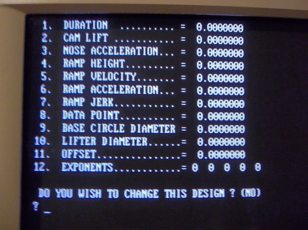
I read a lot for the purpose of learning something new. I may read the same thing over and over until I understand it. That is the purpose of "CAM TALK". You must read and comprehend the material in order to learn something. It's like watching the same movie or video many times and seeing something new each time. I think there is finally enough information on the website now for someone to understand cam profiles and actually design a lobe profile using the proper software. There are definitions, descriptions, and examples for all the terms used in cam profile design. There are actual numbers and range of numbers to use for various parameters. This is all information I have not seen anywhere else on the internet or in books. I share this information because it is not easily found. I remember being very frustrated trying to find this kind of information. It is still frustrating. Many people involved in this stuff seem to be hard to talk with and very hush, hush about sharing knowledge. They will only sell you their knowledge. You must buy their books or pay to go to their seminars. Carefully read all of my posts, take notes. If there is something that you don't understand, ask me. I am not one of those people mentioned earlier. I am glad to share knowledge and help. I know there are not many people that are interested in this stuff but I am a good source of information for those that are. If you are someone who already knows all about this stuff, please contact me and introduce yourself. A little more information on the input data. DURATION - The duration at .050 and the lift are usually already known inputs when designing a cam profile. The duration input number will adjust the duration of the profile. Generally the focus is the duration at .050 but it can be anywhere. The angle on the lift table is 1/4 of the crankshaft duration. NOSE ACCELERATION - The nose acceleration is the lowest acceleration at the nose of the lobe (0-degree). The velocity is decreasing to zero so the nose acceleration is a negative number. The number is usually between -.00015 and -.00035. Changing this number will change the entire profile. Nose acceleration is a main input. RAMPS - The input numbers for the ramps were mentioned in lesson two. The valve closing velocity is usually under 40-inches per second for a modern high-end valve train. Other applications are around 30-inches per second. Tappet lash opening velocities are usually less than .002-inches per degree for a solid tappet. The same ramps can be used with different profile designs. New ramps do not have to be designed for each profile. Save your ramp designs. DATA POINT - This is not necessary to design the lobe, it is just for information. It is the tappet lift at top dead center depending on the indexing of the camshaft in the engine. The angle on the lift table is 1/2 of the crankshaft angle. OFFSET - Amount the lifter bore is machined with a rotational offset to the camshaft lobe. Can be a positive or negative number. Use 0.000 unless the offset is known. EXPONENTS - Used in the mathematical equations in the program to design the cam profile. Changing any exponent will generally affect the entire profile. Each exponent must be different. The first exponent is usually the number two. Exponents are main inputs. My lobe design form will give me the duration, lift, base circle diameter, hydraulic or solid profile, flat or roller tappet, rocker arm ratio, some engine details and the application. That gives me all the information to design the lobe profile. If you like to work with valve lift data, that's fine, just use your valve lift curve and rocker arm ratio and work backwards. The duration input number will determine the duration at .050 (or anywhere). This number is also the angle on the lift table where the ramp and the profile meet. If the ramp has a height of .020, the duration input number will also be the duration at .020. The nose acceleration and the exponents will be the inputs used to "fine tune" the cam profile. The other inputs have already been determined and will not generally need to be changed. As you can see there is no "magic" involved in this. Just a bunch of numbers that will make up the lift and duration of the lobe profile. The velocity, acceleration, and jerk numbers are important to look at and understand how they affect the profile. Any magic is in the cam designer's knowledge and experience. The last and most important step is to make the camshaft. If you are a camshaft grinder, use the lift table to make a model lobe and then a master plate or send the lift table to someone that can CNC a master plate for you. If you have a CNC cam grinder, you know what to do. If you are not a camshaft grinder, send the lift table to someone that can manufacture the camshaft for you. Below is my valve timing sheet to go with the finished camshaft ground on 108-degree lobe separation with 3-degrees advance. 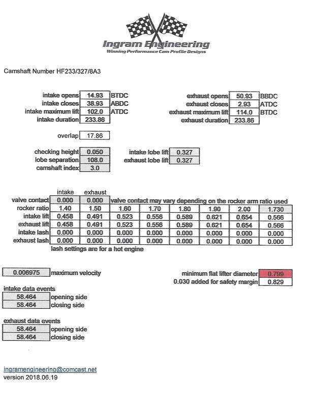 This is an actual Reed profile designed with this software many years ago. It can be used as a starting point and then go in any direction you like. This is the best way to start learning, just plug in different numbers and look at the results. You will eventually see patterns and learn what inputs do what. It was one of the few cam design programs at the time but it works the same as any polynomial program today. If you didn't keep your MS-DOS computer and printer this software will also run using DosBox-X on a modern computer. I am using DosBox-X for these lessons. I put everything on a flash drive and that basically creates a DOS computer on the flash drive. The DosBox-X program is free to download (https://dosbox-x.com/). The last stage in the design process is to combine the four sections together and create the finished lobe profile. The four sections are the (1) opening ramp (2) opening profile (3) closing profile (4) closing ramp. Being able to design each one of these sections separately gives the user a lot more control over the lobe design. Not all programs are written this way. Since this is a symmetrical profile the four sections are not needed but when designing an asymmetrical profile they are very necessary. When designing the ramps and profiles you will need to name and save them. The last stage in the process will use those names. Just follow the program instructions to combine the four sections and create the finished cam profile. The output data will be a graph of the profile and the lift table in 1-degree increments printed on one piece of paper handy for milling a model lobe. The lift table can also be manually programmed into a CNC machine or converted into an .s96 file. The last program (readdata.exe) in the software package will display and print the ramp and profile design data that has previously been saved. Ramps are saved with a .rmp extension and profiles have a .prf extension. Overall the lobe design process is not that difficult but certain profiles can be time consuming to design. Again, it is a trial and error process.
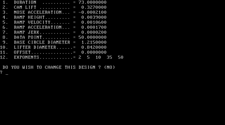
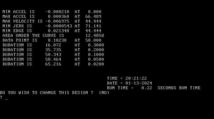
I don't know this to be a fact but I would guess there is some lobe design software that will pretty much design a finished lobe with just a few simple input numbers. It probably wouldn't be affordable but I'm sure one does exists. That type of software would eliminate a lot of knowledge for the person using it. A major problem in the manufacturing industry today. Whatever design software is used the end result is the same. I use the term "maxed out lobe" for a lobe design that has reached all the limitations for the application it was designed for. It doesn't matter how the lobe is created, it is what it is. The lobe could be designed with some super special software program, drawn out on a piece of paper, calculated with a slide-rule, designed with a spreadsheet program, or created out of someone's brain and written on a piece of paper. The finished lobes will all be the same. Once you have reached that maxed out lobe, that's as far as you can go. All the parameters have been reached. The area is the same. The lift curve can only be so steep. Below is the input and some output data for the profile design program. It includes the data from the ramp we just designed. The opening side of the profile will start at the end of the opening ramp and end at the nose of the lobe which is 0-degree. The closing side of the profile will start at 0-degree and end at the beginning of the closing ramp. In this case the opening and closing side of the lobe profile is the same along with the opening and closing ramp (symmetrical). Just like the input data for the ramp design this is also very difficult to teach. You are creating four sections of the cam profile. Another program will put all of the sections together. Scrolling through the lift table and looking at the graph will allow you to analyze the profile and decide if you want to make any changes. Some of the profile input data may be confusing but most of this has been described in previous posts. Be sure to go back and read all of the posts and take notes. This stuff is very difficult to comprehend for someone with no previous experience. Running different numbers and looking at the results is a good way to learn. DURATION = [angle where the ramp and the profile meet, controls the amount of duration] CAM LIFT = [maximum lift of the profile] NOSE ACCELERATION = [minimum acceleration at the nose of the lobe, negative number, affects the entire lobe] RAMP HEIGHT = [data from the ramp design] RAMP VELOCITY = [data from the ramp design] RAMP ACCELERATION = [data from the ramp design] RAMP JERK = [data from the ramp design] DATA POINT = [tappet lift at top dead center, determined by the camshaft centerline] BASE CIRCLE DIAMETER = [of the finished lobe] LIFTER DIAMETER = [face diameter of the flat tappet, N/A for roller tappets] OFFSET = [lifter bore rotational offset to the lobe, usually 0.000] EXPONENTS = [for the polynomial equation, swells or shrinks the area of the profile] To create the profile the input data is giving the the program the starting lift data which is at the end of the ramp, the ending lift which is the maximum lift at the nose of the lobe, the number of degrees between the start and end points which is the duration, and the ending acceleration at the nose of the lobe. The velocity and the jerk are both zero at the the nose of the lobe. The exponents will increase or decrease the rate of the profile and cause the area to increase or decrease. The program will take all of the input data and calculate the tappet lift at each degree of lobe rotation. From the lift table the velocity, acceleration, and jerk can be calculated. Pretty simple stuff, make sense?
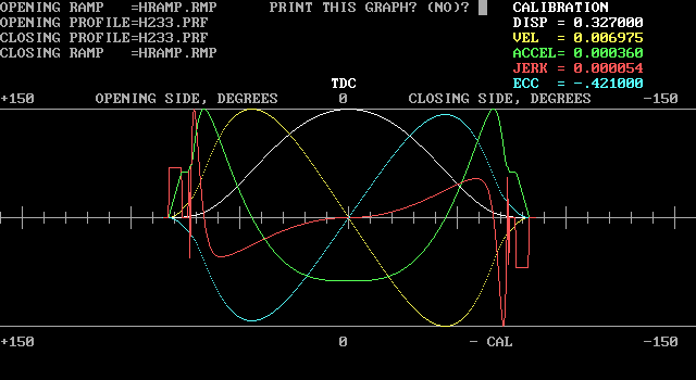
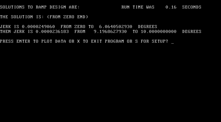
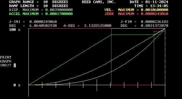
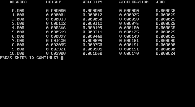
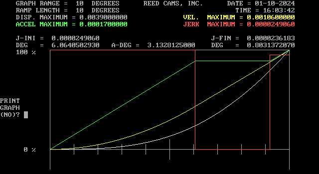
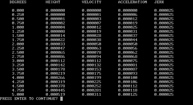
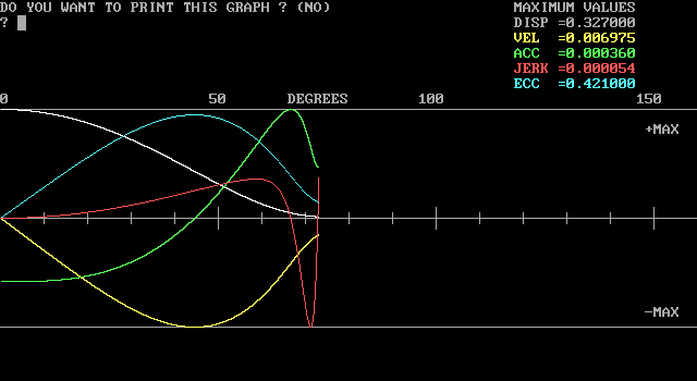 We ended the last lesson with getting ready to design a ramp. Ramps are the entry and the exit areas of the lobe profile. There are very few absolute rules for designing a cam profile. The rules and limitations are usually set by the designer based on their experience. Hence the reason for all the discussion and opinions on the subject. That also applies to the ramps. The opening ramp is pretty simple. It basically leads the tappet into the lobe profile. The opening ramp can almost be as fast as you want. Some profiles don't have an actual opening ramp designed into the profile. The profile ramps are usually noticeable on the velocity curve. They will show as a shallow sloped line on the opening and closing end of the velocity curve. After the opening ramp the tappet will increase in velocity and start accelerating. You can also see this on the velocity and the acceleration curves. The closing ramp is more important because it determines the valve closing velocity against the seat. Too fast and it can bounce the valve off the seat and hurt performance and possibly damage parts. The closing velocity of the valve must be controlled. That is an absolute rule for designing a cam profile. The valve closing velocity is something that will need to be calculated. If the opening ramp has the correct velocity it can also be used as a closing ramp. That will be the type of ramp design for our cam profile. Below are the input numbers for this ramp. Throughout the lessons, click on the picture to enlarge it.  I see everyone's hand go up to ask the same question, "Mr. Ingram, where do those numbers come from?" This is the part that is almost impossible to teach. Kind of like trying to teach someone how to paint a picture. Again, most of this stuff just comes from experience. I use the words "usually" and "generally" a lot because there is no absolute rule for most of this. The profile ramps have a height and a length just like a physical ramp or stairs have a rise and a run. The profile ramps will usually have a height of .020 or less and a length of 20-degrees or less. The velocity and acceleration numbers will obviously be small since the tappet is just starting to move or starting to close. The velocity will usually be .003 or less and the acceleration will be .0003 or less. All of the input numbers have to make sense (compute) to create the ramp and also the profile. All of my numbers are U.S. standard, no metric. duration is in degrees - profile or crankshaft degrees, usually a known input lift is in inches - profile or valve lift, usually a known input velocity is in inches/degree - determined by the tappet face diameter for a flat tappet acceleration is in inches/degree(squared) - usually .0004 or less for maximum jerk is in inches/degree(cubed) - usually less than .00005 for maximum We are now ready to look at the final ramp design. If your input numbers are good, then you are able to proceed. If not, you must try again. You will see a couple of screens including a graph of the ramp. Graphs are a nice way too see a big picture of what's going on. You will also see the lift table of the ramp design on another screen. The ramp and profile lift table can also be displayed in 1/4-degree increments. There are different types of ramps with different names. The engine does not care what type of ramp you use or what you call it. Again, the main thing about ramps is the valve closing velocity. The valve lash is usually part of the ramp but not always. As the lift increases for a given duration the velocity and acceleration numbers will also increase. Further distance to go in less time will always cause an increase in velocity and acceleration.
Cam designers tend to develop their own style and approach just as any skilled craftsman will do. I was very fortunate to learn this stuff while working at a major camshaft manufacturing company. I had access to highly sophisticated measuring devices and was able to analyze different camshafts from many manufacturing companies. That taught me a lot by being able to see how other camshaft companies were designing their lobes. I would recommend to everyone wanting to pursue this stuff to get a good "cam doctor" machine and measure as many different camshafts as you can. Along with a design program you will be able to duplicate or create your own designs after you acquire a basic understanding of lobe design. Welcome everyone, sit anywhere you like. These first lessons will be a simple introductory approach to the cam profile design process using data and images from the design software. I would recommend taking notes, there will be too much information to try and remember. The two main programs of the software package are the ramp design program (ramplatb.exe) and the profile design program (prof386d.exe). Another main program (camplotd.exe) will create the finished lobe profile after you successfully design the opening and closing ramps and the opening and closing profiles. I say successfully because this entire process is trial and error until the desired lobe design is reached. If the numbers you enter do not compute, you can not continue. I usually design the ramps first. The ramp is just that, a ramp. I like to use examples to help explain stuff. A motorcycle jump is an easy way to visualize a ramp. There is a launching ramp and a landing ramp. Each ramp is designed for a particular task. In cam design sometimes the opening and closing ramps will be the same. Sometimes the opening and closing profiles will be the same. This is known as a symmetrical profile, same opening and closing. We will design a symmetrical profile since it is simpler. It will be a hydraulic flat tappet profile for a small block Chevrolet 350 V8 engine. Below is the ramp design input screen. The ramp will begin at zero tappet lift and end at some point that you choose. These input numbers are for the end of the ramp. DISPLACEMENT = [tappet lift at the end of the ramp] VELOCITY = [at the end of the ramp] ACCELERATION = [at the end of the ramp] LENGTH = [length of the ramp in degrees] D.F. JERK = [degrees of final jerk at the end of the ramp, enter "A" and the program will automatically calculate the final jerk and the number of degrees]  click on picture to enlarge Some designers don't pay a lot of attention to the ramp design. It's probably not as important today with better valve springs and a more ridged valve train. When I started designing, the ramp design was important, so I still pay close attention to it. The most important part is how fast the valve closes against the seat. Obviously engine rpm, rocker arm ratio, and valve lash will need to be taken into consideration when designing the ramps. I keep a library of various ramp designs for different applications. Ramps that I have designed and used over the years and some that are taken from camshafts that I have analyzed. A lobe can actually be designed without ramps. Many of the original 3-arc cam profiles did not have ramps. Later with 6-arcs they did include ramps. Some modern profiles are designed without an opening ramp. Just like the lobe profile, the ramps are created by the designer. Just like the lobe profile, it is a trial and error process. It all comes with time and experience. Don't get discouraged. Wishing everyone a better year than what has come before. Thank you to all my customers that have trusted me to design your cam profiles. Nice to have met new folks interested in this stuff. Let me know what you think about the online cam profile design class.
I have been asked a few times about teaching automotive cam profile design. I enjoy sharing knowledge with like minded people but I don't have a logical way of actually teaching someone in person. I was thinking maybe I can do this online through the website. I don't have any desire to create a YouTube channel but I admit that would probably be the best approach.
I have an old 1980's DOS lobe design program that is for sale on the website. A very good program at the time, just a little hard to use today. I hate to see it go to waste so this may be a way to make use of it again. I would also like to keep the Reed cam profiles alive in the process. I know many customers thought that the Reed cam profiles were some of the best. Maybe some of those folks would be interested in this. I am thinking about using the program to help teach cam profile design. I would go through the design process with Reed profiles and post it here on the website. It would be free to everyone but to really receive the full benefit the reader would also need to have the program. Once they becomes proficient with the program they may decide to pursue this further and purchase a more modern program and even start their own camshaft manufacturing company. Apparently in the world of flat tappet camshafts the quality of the camshafts and/or the lifters has turned to absolute crap. I am not surprised and can see this happening since flat tappet camshafts are no longer used in production automotive pushrod engines. Basically it's the same thing that happened with the automotive engine oil many years ago. The chemical make-up of the oil was changed because the production car engines went to using roller camshafts and a different oil recipe was created than what was used with flat tappet camshafts and that oil became obsolete. Since flat tappet camshafts are no longer used there is not the quality control for these components that was there before. I would guess the major camshaft core suppliers will eventually quit manufacturing them. The racing industry only makes up a small part of the entire automotive industry. If you haven't figured it out yet, it's all about money.
I would guess the material make-up and/or the metallurgy has changed in the flat tappet components. Finding short-cuts in order to manufacture the components cheaper would obviously be the reasoning behind it. Manufacturing flat tappet camshaft cores and lifters is a very small segment of the automotive industry since the major car companies don't use them anymore. It's not worth the investment. Simple economics. Simple economics also needs to be used to fix the problem. Racers and engine builders must unite together and protest against the flat tappet camshaft rules and refuse to use them. It will not take long before the race tracks will change the rules and allow roller camshafts to be used. Simple economics. Sometimes fast rate, slow rate, or aggressive might be the term used. Like most camshaft terms, they are used in marketing to sell camshafts. What makes a cam profile fast rate or slow rate? What makes a cam profile aggressive? Sometimes the term only applies to the profile ramps, such as the ramps are fast or the ramps are slow, the ramps are aggressive.
If you look at enough cam profiles, some definitely move the valve faster than others. Basically the movement of the valve (or tappet) per degree of lobe rotation is considered the cam profile rate. Velocity is the actual term used when designing cam profiles. How quickly that velocity is reached is the acceleration which is also part of the rate. In flat tappet profiles the maximum velocity is determined by the tappet face diameter. Roller profiles will usually have a faster maximum velocity and most are about the same for a specific profile. The acceleration will need to be controlled on a roller profile to prevent excessive negative radius in the flanks. Some ramps will open the valve faster, some ramps will close the valve slower. It's just all part of the design. If someone is trying to sell you a camshaft that has fast ramps than slow ramps are bad. If the maximum velocity is higher than it is better. Sound familiar. If you give-in to this type of marketing, read my last post. Maybe read it a few times, it is very short and to the point. The best way to compare cam profile rates is by looking at the duration at the higher lifts. There is a reason most camshaft manufacturers do not publish duration figures past 0.050 tappet lift. Measure the duration at 0.100 intervals. Compare the duration numbers. If the camshafts are the same at 0.050 but one is larger at 0.100, 0.200, 0.300, and so on, the larger one has a faster rate. More importantly, it has a faster rate where is really matters. The faster rate at the higher lifts gives you more area under the lift curve. What goes on above 0.050 on a cam profile is a whole lot more important than what goes on below 0.050 as far as making power. Below 0.050 has more to do with the affect the cam profile has on the valve train (valve springs, push rods, valve seats, valve lash, etc.) In a four stroke internal combustion engine turning 6000 rpm the valves are opening and closing 50 times a second. At 10,000 rpm that number increases to 83 times a second. Don't overthink this stuff or pay much attention to the latest marketing gimmicks.
My understanding is the best CNC machines are accurate out to five decimal places. I saw some numbers like 0.00007. When we would cut lobe models on manual milling machines we were able to go out to five decimal places using a large diameter 0.0001 dial indicator. The fifth decimal place was a "precise estimate" by the operator.
You might wonder why do cam profile lift tables go out to eight decimal places since the best machines are only good to five decimal places? The eight decimal places are necessary to create a smooth velocity, acceleration, and jerk curve for the cam profile design. With five decimal places the curves are very jagged and hard to analyze. The lift and velocity curves are really the only curves that will work with five decimal places but to properly design a cam profile, smooth acceleration, and jerk curves are also necessary. Since the cam profile is designed to eight decimal places and only machined to five decimal places the finished lobe profile is not exactly the same as the design, very close but not exactly the same. The old manually made lobe models were even farther away from the design but still worked just fine. I use this saying all the time: "There are three cam profiles: (1) the original design, (2) the finished lobe, and (3) the cam profile in a running engine." All three are different. Don't get caught-up in worrying about numbers being exact. I appreciate the comments received on my posts. I now receive more spam than actual comments so I have disabled the comment feature. I may enable it again in the future to see how things go. Please send me an email or call with any suggestions or comments you have. Thank you.
Updated June 23, 2023 - The comment feature is enabled so please be sure to use it. I was also able to restore all the old comments.  What actually is the cam profile? In the beginning, the 3-arc type cam profile was a lobe shape that had some dimensions on it like a blueprint. You could then physically machine the cam lobe shape from the dimensions. Anyone can create a cam profile this way. The only thing you know for sure about the finished cam profile is the maximum lift. None of the other data will be known until the cam profile is actually made and then measured. Changing the dimensions of the arcs will change the measured data. The 3 arcs are the (1) base circle diameter, (2) the nose(tip) radius, and the (3) flank(side) radius. The distance between the base circle and the nose will obviously determined the maximum lift. The lift of the tappet at various places is measured out to four decimal places and the duration and velocity data is then calculated. That will usually provide enough data to know if the profile will work for the application. As the need for more control over the cam profile increased the number of arcs also increased. I am not sure but it looks like six different arcs were eventually used. That allowed some type of ramps to be integrated into the profile. An overall slow process but it worked. Remember a low rpm engine with light valve spring pressure is very forgiving to the cam profile design. This was all done before computers and involved mathematical equations were used to design the cam profile.
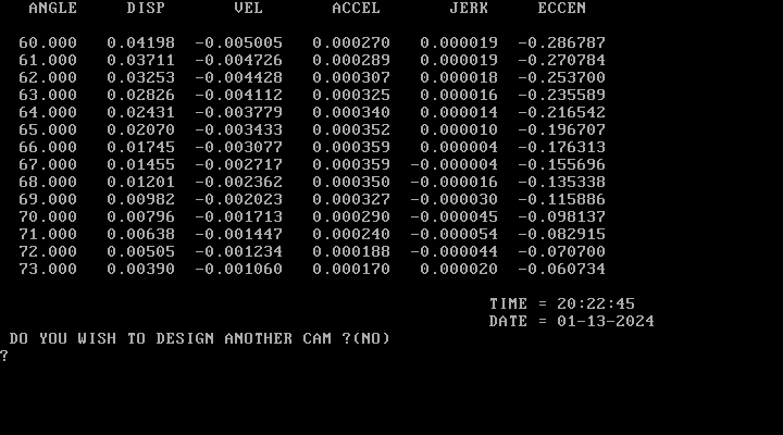
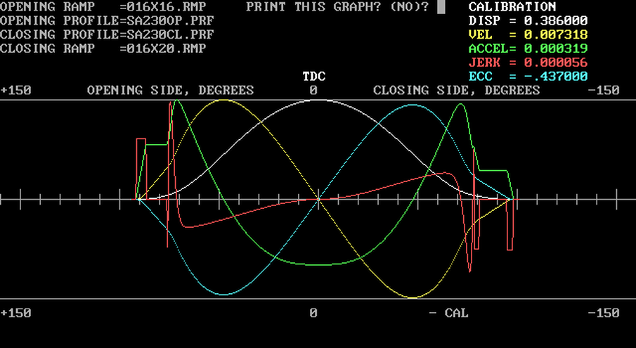
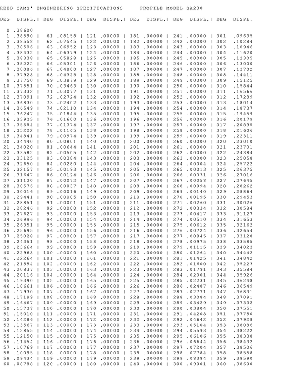
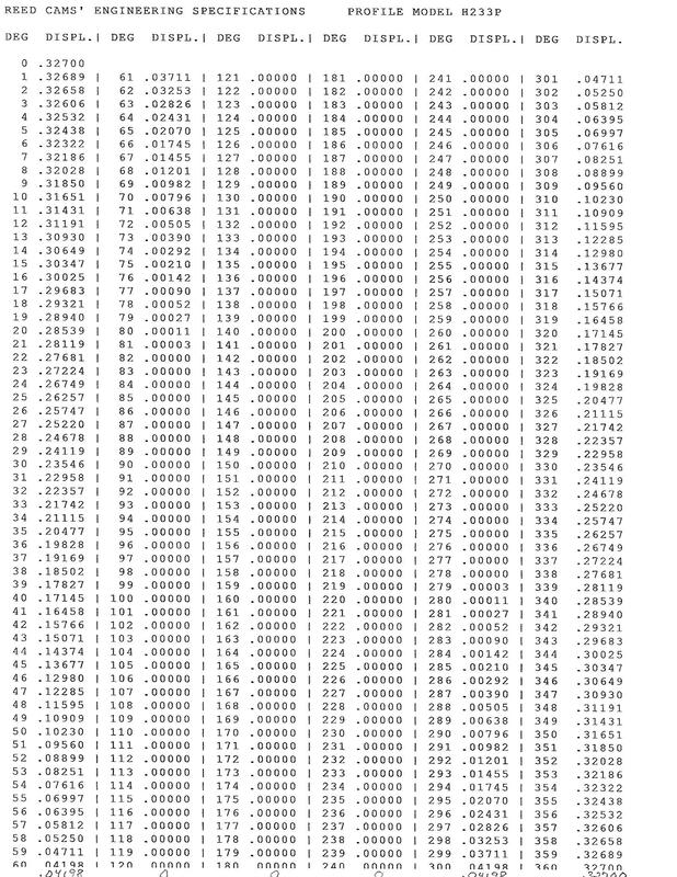
With computers a cam profile lift table can be created out to at least six decimal places. This lift table IS THE CAM PROFILE and can tell you almost everything you need to know. You just have to know how to read it. Below is a sample lift table on the opening side of a cam profile. There will also be one for the closing side. In this example they are the same (symmetrical cam profile). 0 0.4200000 1 0.4198850 2 0.4195400 3 0.4189650 4 0.4181600 5 0.4171250 6 0.4158601 7 0.4143653 8 0.4126406 9 0.4106862 10 0.4085022 11 0.4060888 12 0.4034464 13 0.4005754 14 0.3974762 15 0.3941494 16 0.3905959 17 0.3868165 18 0.3828125 19 0.3785850 20 0.3741358 21 0.3694665 22 0.3645793 23 0.3594766 24 0.3541612 25 0.3486360 26 0.3429046 27 0.3369709 28 0.3308390 29 0.3245139 30 0.3180007 31 0.3113052 32 0.3044337 33 0.2973929 34 0.2901904 35 0.2828341 36 0.2753327 37 0.2676954 38 0.2599321 39 0.2520534 40 0.2440706 41 0.2359955 42 0.2278409 43 0.2196199 44 0.2113466 45 0.2030356 46 0.1947023 47 0.1863625 48 0.1780327 49 0.1697300 50 0.1614721 51 0.1532769 52 0.1451628 53 0.1371486 54 0.1292531 55 0.1214954 56 0.1138944 57 0.1064687 58 0.0992368 59 0.0922166 60 0.0854250 61 0.0788782 62 0.0725911 63 0.0665770 64 0.0608476 65 0.0554124 66 0.0502788 67 0.0454511 68 0.0409312 69 0.0367175 70 0.0328051 71 0.0291854 72 0.0258463 73 0.0227722 74 0.0199441 75 0.0173400 76 0.0149365 77 0.0127169 78 0.0106757 79 0.0088146 80 0.0071388 81 0.0056538 82 0.0043632 83 0.0032667 84 0.0023599 85 0.0016333 86 0.0010727 87 0.0006597 88 0.0003725 89 0.0001874 90 0.0000799 91 0.0000262 92 0.0000054 93 0.0000004 94 0.0000000 The table lists the tappet lift at each degree of camshaft rotation. The first column is the degree of rotation and the second column is the tappet lift. Zero degree is the maximum lift of the cam profile. Do you know the duration at 0.050 for this profile? If you don't, you need to start at the beginning and carefully read all of my entries. The change in lift from one degree to the next is velocity. The change in velocity is acceleration. The change in acceleration is jerk. All these are important parameters to look at when analyzing a cam profile. A lift table with a resolution of at least six decimal places is necessary to adequately analyze these parameters. The lift table can be inserted into a spreadsheet program and these numbers can be calculated. A graph(curve) can then be created from these numbers. Lift, velocity, acceleration, and jerk curves can tell much about the cam profile design. If you have a computer camshaft lobe profiler or looked at a profile report, this is the kind of data you will see. Many engine builders use this data to help decide on which camshaft to use. The ramp designs and valve lash settings can also be analyzed. I also like to know the radius of curvature data and pressure angle data. That data is not always part of the lift table but should be available in the profile report. As I said, the lift table is the cam profile. The lift table is the piece of data that you want to have. It will be able to tell you important information about the cam profile along with the ability to actually manufacture it. How the lift table is created is really not important. There are different ways the lift table can be created. The 3-arc cam profile talked about earlier could be computer profiled and the lift table created. Different cam profile design programs can create the lift table. The type of program used does not matter. On valve trains with a variable rocker ratio the valve lift data is designed first and then converted to the lobe lift table. The original cam profile design or an actual lobe should have a lift table that can be analyzed to determine if the cam profile design is a good one or a not so good one. If you have a lift table or .s96 file that you would like analyzed, email it to me and I will give you my honest opinion on the cam profile design. The answer to the duration at 0.050 question is 264.23 degrees at the crankshaft. I have listed an early MS-DOS cam profile design program for sale on the "ORDER" page. I have had this program for many years and hate to see it just go to waste. Hopefully it can help those that want to continue learning and understanding about automotive cam profile design. It is a multiple part program consisting of a ramp design program, a profile design program, and a program that combines the opening and closing ramps and profiles to create the finished cam profile design. There is another program that will display and print the profile lift table and graphs. These programs were written in the 1980's for John Reed by Vantur Electronics, Inc. in Atlanta, Georgia. Larry A. Turner was the computer genius who wrote the programs and was a friend of John's. The programs were revised over the years with these being the last version. Reed Cams, Inc. was a major sponsor of NASCAR in the 1980's. Many of those race cars were running a Reed camshaft and also a Reed carburetor. The camshaft profiles being used at the time were all designed by this software. Remember this is before CNC machines, there is no .s96 or Landis .p file. The output file is the lift table formatted for milling a model lobe. Not to worry, the lift table can be manually programed into any CNC machine or converted into an .s96 file. Remember the lift table is the cam profile. Be sure you have the necessary computer skills to operate these old programs. No refunds. Contact me with any questions.
 output lift table formatted for milling a model lobe 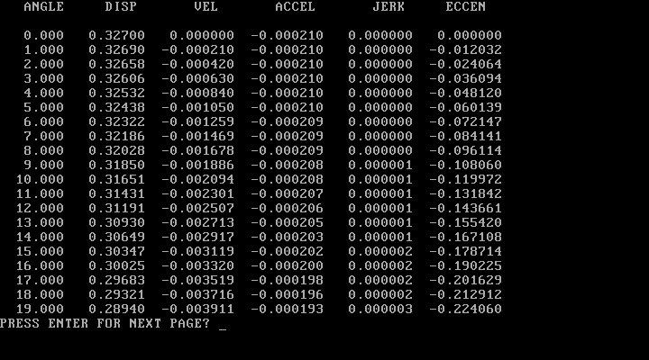 output profile data (also available in 0.25-degrees)
For those interested in the mathematical equations of cam profile design this post is for you. I remember searching the internet for information on cam profile design and only being able to find information on the mathematics involved. This was not really what I was interested in so I started "Cam Talk" to help others interested in cam profile design and pass on more practical knowledge. As I have said many times before the software does the math for you. It does not teach anything about cam profile designs. That information seems to be very difficult to find.
These videos get into the math involved in designing a cam profile. I thought the instructor did an excellent job of presenting this. Here is a link to the beginning of the series to get you started. This stuff is not that interesting to me and I am certainly no mathematician but it is part of the process. Like I said, that's what the software does. Some do enjoy the math so this is for you. youtu.be/mgPU3Ba9_sA I wanted to add this since my previous post sounded like I did not want to teach how to design a cam profile. I just do not think I have the ability to do so. Each camshaft application has its own limitations on cam profiles. I am certainly not an expert on every application (not even one). That comes from years of experience working with each particular application. You learn from trial and error on how far you can push the limitations. It is difficult to teach that especially if you do not know the limitations. Limitations tend to also change as valve train materials become lighter and stronger.
I have no problem sharing knowledge. That is why I write these posts. If you are someone that has a cam design program and has a specific question, I will be glad to answer it if I can. Trying to learn about cam design without actually doing it is difficult to do. Sort of like learning to ride a motorcycle without actually riding it. There is much to learn about cam profiles without knowing how to design one. That is what I really try to do here on Cam Talk. If you have really read each one of my posts and halfway comprehended them, you should have a pretty good foundation about cam profiles. You should certainly have more knowledge than most people. Unfortunately you still do not know how to design a cam profile. I don't think I can teach you that. I don't think anyone can actually teach you that. Harvey Crane (of Crane Cams) had a class that he offered. He is the only one I know of that has done that.
There are many applications for designing a cam profile. We only think about engines and camshafts. Most applications are in the industrial world and have nothing to do with engines and camshafts. We never think about that world and they never think about our world (engines and camshafts). They are two totally different applications. The same math is used in both applications. That's why it is so hard to find information on specifically automotive cam profile designs. It's actually a small percentage of cam profile applications and not many people do it. Most of the information is focused on the math involved in designing an industrial cam profile (the shape). Again, the same math is used to design an automotive cam profile, the application doesn't matter. Any mathematician can design an industrial cam profile. He can not design an automotive cam lobe unless he has more knowledge than just the math. The engine camshaft profile has many unique rules and limitations that are not encountered in the industrial world. All that is stuff the mathematician will need to learn for the engine and camshaft world. That is the stuff that is hard to teach. Most mathematicians have never designed an automotive camshaft profile and never will, but they are all over the internet telling us how it should be done. The computer software does the math part for you. You can teach someone how to use the software. The software does not know a good profile from a bad profile. The person using the software has to know that. That is hard to teach. It basically comes from years of experience. You are an automotive cam profile designer once you have designed many cam profiles, had camshafts manufactured with your cam profile designs, run the camshaft in an actual engine, and made good power and reliability for the applications the profiles were designed for. One last thing, someone needs to pay you for your cam profile designs. In reality, there are very few of us. Inverted flank is another cam profile term that you may not have heard of or understand. Like most camshaft terms it is used as a marketing tool to sell camshafts.
Inverted flank profiles are roller cam profiles that have a negative radius or concave shape on the side (flank) of the profile. Kind of like a dip in the road. Depending on the severity of the dip, it may not cause a problem or it may cause a big problem. These are only on roller profiles, not flat tappet profiles. When lift is increased for a given cam profile, velocity and acceleration also increases. Duration will stay the same but the distance to travel is farther. This obviously causes the tappet to have to move faster. In a flat tappet profile the natural design tendency will end up with a smaller radius at the nose of the lobe. This is a limitation. The nose radius can only be so small. The velocity will also become too fast for the diameter of the tappet face. Another limitation. In a roller tappet profile the natural design tendency will end up with a negative radius in the flank (or flanks) of the profile. A limitation caused from the acceleration increasing. There are techniques that can be used for both flat tappet and roller profiles that will help the designer control these limitations. Some designers use them, some do not. For those that do not their cam profiles will be limited in area or they end up being very rough and maybe damaging to the valve train. The flat tappet profile limitations are pretty straight forward. You end up with a cam profile that has a sharp nose and runs off the edge of the tappet face if the limitations are ignored and not controlled. The roller tappet profile will eventually have a negative radius (the dip in the road) that is just too small to actually grind. The standard grinding wheel diameter on a camshaft grinder is 18-inches. That will have a 9-inch radius. It is possible to get smaller grinding wheels. Having ground camshafts for many years, I know this is a real pain to do. Grinding slightly inverted profiles is still a pain even with the standard 18-inch wheel. It really slows down the process and the camshafts usually cost more. The customer may not be too concerned about this, he wants to know if they will make more power. The answer is no. More times than not they are much harder on the valve train. Remember the dip in the road. A smooth road is much easier to drive on. Slightly inverted cam profiles may not be as hard on the valve train but they are still a pain to grind and there is no advantage in performance. Some of the camshaft marketing will try to tell you different. Using the proper software and techniques to design a non-inverted roller profile will always produce a better cam profile. |
||||||||||||||||