|
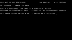
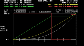
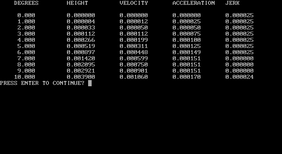
We ended the last lesson with getting ready to design a ramp. Ramps are the entry and the exit areas of the lobe profile. There are very few absolute rules for designing a cam profile. The rules and limitations are usually set by the designer based on their experience. Hence the reason for all the discussion and opinions on the subject. That also applies to the ramps. The opening ramp is pretty simple. It basically leads the tappet into the lobe profile. The opening ramp can almost be as fast as you want. Some profiles don't have an actual opening ramp designed into the profile. The profile ramps are usually noticeable on the velocity curve. They will show as a shallow sloped line on the opening and closing end of the velocity curve. After the opening ramp the tappet will increase in velocity and start accelerating. You can also see this on the velocity and the acceleration curves. The closing ramp is more important because it determines the valve closing velocity against the seat. Too fast and it can bounce the valve off the seat and hurt performance and possibly damage parts. The closing velocity of the valve must be controlled. That is an absolute rule for designing a cam profile. The valve closing velocity is something that will need to be calculated. If the opening ramp has the correct velocity it can also be used as a closing ramp. That will be the type of ramp design for our cam profile. Below are the input numbers for this ramp. Throughout the lessons, click on the picture to enlarge it. I see everyone's hand go up to ask the same question, "Mr. Ingram, where do those numbers come from?" This is the part that is almost impossible to teach. Kind of like trying to teach someone how to paint a picture. Again, most of this stuff just comes from experience. I use the words "usually" and "generally" a lot because there is no absolute rule for most of this. The profile ramps have a height and a length just like a physical ramp or stairs have a rise and a run. The profile ramps will usually have a height of .020 or less and a length of 20-degrees or less. The velocity and acceleration numbers will obviously be small since the tappet is just starting to move or starting to close. The velocity will usually be .003 or less and the acceleration will be .0003 or less. All of the input numbers have to make sense (compute) to create the ramp and also the profile. All of my numbers are U.S. standard, no metric. duration is in degrees - profile or crankshaft degrees, usually a known input lift is in inches - profile or valve lift, usually a known input velocity is in inches/degree - determined by the tappet face diameter for a flat tappet acceleration is in inches/degree(squared) - usually .0004 or less for maximum jerk is in inches/degree(cubed) - usually less than .00005 for maximum We are now ready to look at the final ramp design. If your input numbers are good, then you are able to proceed. If not, you must try again. You will see a couple of screens including a graph of the ramp. Graphs are a nice way too see a big picture of what's going on. You will also see the lift table of the ramp design on another screen. The ramp and profile lift table can also be displayed in 1/4-degree increments. There are different types of ramps with different names. The engine does not care what type of ramp you use or what you call it. Again, the main thing about ramps is the valve closing velocity. The valve lash is usually part of the ramp but not always. As the lift increases for a given duration the velocity and acceleration numbers will also increase. Further distance to go in less time will always cause an increase in velocity and acceleration. Cam designers tend to develop their own style and approach just as any skilled craftsman will do. I was very fortunate to learn this stuff while working at a major camshaft manufacturing company. I had access to highly sophisticated measuring devices and was able to analyze different camshafts from many manufacturing companies. That taught me a lot by being able to see how other camshaft companies were designing their lobes. I would recommend to everyone wanting to pursue this stuff to get a good "cam doctor" machine and measure as many different camshafts as you can. Along with a design program you will be able to duplicate or create your own designs after you acquire a basic understanding of lobe design.
0 Comments
Leave a Reply. |
Archives
July 2024
|


