|
I don't know this to be a fact but I would guess there is some lobe design software that will pretty much design a finished lobe with just a few simple input numbers. It probably wouldn't be affordable but I'm sure one does exists. That type of software would eliminate a lot of knowledge for the person using it. A major problem in the manufacturing industry today. Whatever design software is used the end result is the same. I use the term "maxed out lobe" for a lobe design that has reached all the limitations for the application it was designed for. It doesn't matter how the lobe is created, it is what it is. The lobe could be designed with some super special software program, drawn out on a piece of paper, calculated with a slide-rule, designed with a spreadsheet program, or created out of someone's brain and written on a piece of paper. The finished lobes will all be the same. Once you have reached that maxed out lobe, that's as far as you can go. All the parameters have been reached. The area is the same. The lift curve can only be so steep.
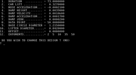
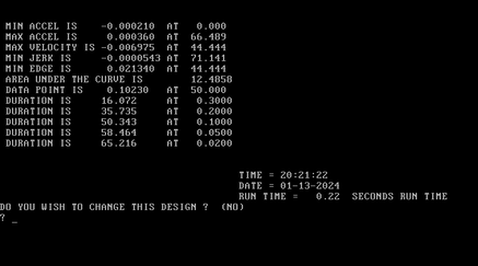
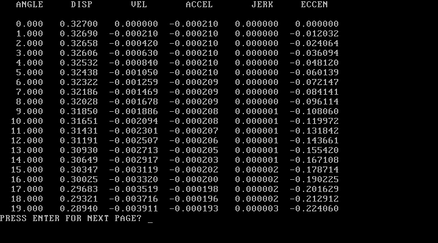
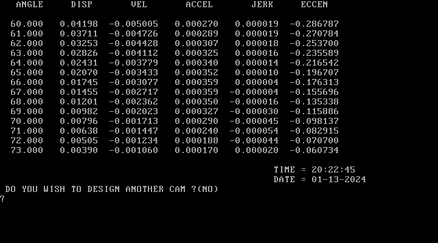
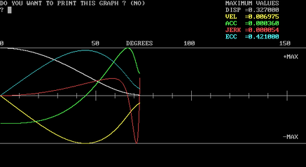
Below is the input and some output data for the profile design program. It includes the data from the ramp we just designed. The opening side of the profile will start at the end of the opening ramp and end at the nose of the lobe which is 0-degree. The closing side of the profile will start at 0-degree and end at the beginning of the closing ramp. In this case the opening and closing side of the lobe profile is the same along with the opening and closing ramp (symmetrical). Just like the input data for the ramp design this is also very difficult to teach. You are creating four sections of the cam profile. Another program will put all of the sections together. Scrolling through the lift table and looking at the graph will allow you to analyze the profile and decide if you want to make any changes. Some of the profile input data may be confusing but most of this has been described in previous posts. Be sure to go back and read all of the posts and take notes. This stuff is very difficult to comprehend for someone with no previous experience. Running different numbers and looking at the results is a good way to learn. DURATION = [angle where the ramp and the profile meet, controls the amount of duration] CAM LIFT = [maximum lift of the profile] NOSE ACCELERATION = [minimum acceleration at the nose of the lobe, negative number, affects the entire lobe] RAMP HEIGHT = [data from the ramp design] RAMP VELOCITY = [data from the ramp design] RAMP ACCELERATION = [data from the ramp design] RAMP JERK = [data from the ramp design] DATA POINT = [tappet lift at top dead center, determined by the camshaft centerline] BASE CIRCLE DIAMETER = [of the finished lobe] LIFTER DIAMETER = [face diameter of the flat tappet, N/A for roller tappets] OFFSET = [lifter bore rotational offset to the lobe, usually 0.000] EXPONENTS = [for the polynomial equation, swells or shrinks the area of the profile] To create the profile the input data is giving the the program the starting lift data which is at the end of the ramp, the ending lift which is the maximum lift at the nose of the lobe, the number of degrees between the start and end points which is the duration, and the ending acceleration at the nose of the lobe. The velocity and the jerk are both zero at the the nose of the lobe. The exponents will increase or decrease the rate of the profile and cause the area to increase or decrease. The program will take all of the input data and calculate the tappet lift at each degree of lobe rotation. From the lift table the velocity, acceleration, and jerk can be calculated. Pretty simple stuff, make sense?
0 Comments
Leave a Reply. |
Archives
July 2024
|
